


 Durcor
Supports
| Maximum Support Spacing for Uninsulated Pipe | |||
|---|---|---|---|
| *Maximum mid-span deflection 1/2" with a specific gravity of 1.0 | |||
| Size (in) |
Continuous Spans of Pipe (ft)(1) | ||
| 75°F | 150°F | 300°F | |
| 1 | 11.1 | 10.5 | 9.3 |
| 1-1/2 | 12.7 | 12.1 | 10.7 |
| 2 | 13.6 | 13.0 | 11.4 |
| 3 | 16.6 | 15.9 | 14.0 |
| 4 | 18.3 | 17.5 | 15.4 |
| 6 | 21.5 | 20.6 | 18.1 |
| 8 | 24.1 | 22.9 | 20.2 |
Proper pipe support spacing depends on the temperature and weight of the fluid in the pipe. The support spacing table is based on unrestrained continuous beam theory using the pipe bending modulus. The maximum span lengths were developed to ensure a design that limits mid-span deflection to 1/2 inch and dead weight bending to 1/8 of the ultimate bending stress. Any additional loads on the piping system such as insulation, wind, seismic, etc., require further consideration. Restrained (anchored) piping systems operating at elevated temperatures may result in guide spacing that is shorter than unrestrained piping systems. In this case, the maximum guide spacing governs the support span requirements for the system. Pipe spans near elbows require special attention. Both supported and unsupported elbows are considered in the following tables and must be followed to properly design the piping system.
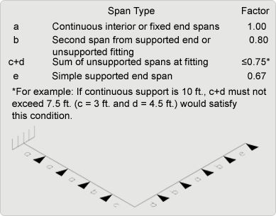
Adjustment Factors for Various Spans With Unsupported Fittings at Change in Direction
| Support Spacing vs. Specific Gravity | |||||||
|---|---|---|---|---|---|---|---|
| Example: 3” pipe @ 150 °F with a 1.5 specific gravity fluid, maximum support span spacing = 22.9 × 0.90 = 19.8 feet. |
|||||||
| Specific Gravity | 3 | 2 | 1.5 | 1.25 | 1 | 0.75 | Gas/Air |
| Multiplier | 0.76 | 0.84 | 0.9 | 0.95 | 1 | 1.07 | 1.4 |